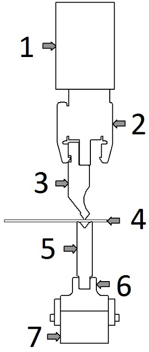
1 – Upper Beam
The upper beam is an integral part of the press brake and features a kind of rail which the punch holder will mount to. On down acting brakes this is the part of the machine that moves, transferring power to the work piece.
4 – Punch Holder
The punch holder attaches semi-permanently to the upper beam and serves to hold a variety of punches. They come in two basic forms, European and American, understanding the difference is important. See our post on European Vs. American Style Tooling for more information. Punch holders will typically have a built in shimming mechanism for balancing them with the lower die.
3 – Punch
Punches are the upper part of the tooling system and are classified by their Tip Angle, Relief Shape and their Installed Height. Standard Tip Angles are 30 °, 45 °, 60 °, 75 °, 88 ° and 90 °. The 30 ° and 45 ° types are known as acute punches. 60 ° and 75 ° Punches are used for Air Bending. 88 ° and 90 ° Punches are used for Bottom Bending. 90 ° Punches will be used for Coining. The relief shape allows for return bends to fold into the punch area.
The installed height of press brake tooling is the distance from the tip of the punch to where it contacts the upper beam / holder. For European Tooling there are 7 standard heights. 65mm, 67mm, 70mm, 90mm, 95mm, 104mm, and 105mm.
Punches come in two styles when connecting to the upper holder, European Style and American Style. European Tooling has an offset holder (as shown above) where American Tooling has an inline holder. Check our post on tooling styles for more information.
When bending deep boxes which have long flanges around a base tab you’ll want to investigate different tooling options. Some are basic such as extending the punch holder and some are a bit mroe creative such as window bending and 30-60 bending. For more information look into this post on Box Bending.
4 – Work Piece
Commonly referred to as the work piece the sheet metal being bent is the driving force for all tooling selection. The type of material, its mechanical properties and the intended bends drive all other aspects of the tooling set up. Sheet metal is classified by it’s material and its gauge. The gauge is a numerical value assigned to the thickness of the metal. See our Gauge Chart for a better understanding of gauges and tolerances.
5 – Die
The bottom section of the tooling is known as a die. Dies are classified by the shape of the groove, the number of grooves and the height of the die. The most common shape of die is a v die, which, as its name suggests, is a block of tooling steel which has a v shaped groove cut into it. A v die with a single groove is known as a 1V Die, dies with two grooves are known as 2V Dies and so on. 2V Dies will always feature the same angle on both grooves to prevent accidental damage, however the v opening size will typically be different. This allows an operator to quickly switch from bending a light gauge to bending a heavy gauge without having to retrieve a new die. Second to v dies the most common type is a U Die. U dies feature a rectangular cutout with 45 ° chamfered edges and flat tops. Because of this geometry U Dies lend themselves to having grooves cut into more than one side of the die. It’s not uncommon to see a 3U Die. There is much more information on 3 sided dies here.
6 – Rail
The rail is a manufactured piece of tooling which is attached to the press brake and holds various dies. The rail typically features a protrusion or groove which matches with the die set. This piece of tooling allows you to level and straighten a single piece of tooling and then interchange dies with confidence.
7 – Lower Beam / Die Holder
The lower beam is part of the actual press brake which features a kind of vice clamp for holding the raid or die set. On up acting brakes the lower beam is moves upward to bend the metal. When inspecting and maintaining your brake it is crucial to make sure the lower beam is clean and level in relation to the punch holder.
Basic Requirements
First the tooling should be of a size and weight which allows for handling, installation and removal. Unless you have a fully automated system there will be an operator responsible for setting up the Brake Press, taking this into account is important to selecting your tooling. Second to the safety of the operator is the accuracy of the tooling geometry. Variance in the tooling geometry will directly contribute to under or over bending of the work piece, or in extreme cases the damaging of the tooling. Due to the high tonnages involved in bending any imperfections on the surface of the punch or die can transfer to the workpiece. Third the tooling should have excellent strength and wear resistance. Typically heat treatment is applied to all Brake Press tooling, greatly improving its hardness, strength and subsequently its resistance to fatigue. Finally your tooling should be interchangeable between your machines. There are two basic types of tooling for Brake Presses, American and European, consider which type of machinery and holders you have before purchasing new tooling.
Tooling Strength
During the bending process the tooling will undergo both compressive forces and bending moments. The repetitive nature of bending operations the necessity for high strength and wear resistance demands quality steel properly heat treated. When heat treating steel there are two methods, hardening and thermal refining. To be referred to as tooling the piece should be treated by one of these methods. Strictly speaking punches and dies made from raw, untreated, metal should not be referred to as tooling because it will not be effective when bending.
Hardened Tooling:
Two common steels used for Brake Press tooling are Chromium Molybdenum Steel, Type 4 (SCM4) and Yasuki Steel. Chromium Molybdenum Steel is a structural steel used in aircraft parts, weapon components, roll cages and structural car parts in addition to their use in tooling. The steel is used for Brake Press tooling because of its receptiveness to heat treatment. Typically this steel will obtain a HRC of 43 to 48 when treated for tooling. Yasuki Steel is a product of the Japanese company Hitachi and is made from very high quality iron sand. It has one of the highest purities in commercial steel and is used in knives in addition to tooling. Like SCM4 Yasuki Steel is very receptive to hardening by heat treatment. Surface treatments like Wilson Tool’s Nitrix Coating can bring the surface hardness of tooling to HRC 70, further preventing wear of the tool’s geometry.
The manufacturing process of hardened steel tooling is typically a 4 step operation; Forming, Hardening, Correcting and Finishing. First the tool profile is created from the stock material. Extra material is left on to be removed later. The majority of the machining and forming is before the hardening stage because after the tool has been hardened it will be difficult to work with. The tooling is then hardened. Because of the high heat the hardening process the tool will not finish with the exact profile as before hand so additional correcting is done before the tool is finished. The tool’s critical areas such as the punch tip and v-opening are then ground by precision grinders, typically using diamond or CBN coatings. On a die with a multiple v-opening the different v’s are often ground together from one wheel.
Thermally Refined Tooling:
Steel used for thermally refined tooling is typical a Carbon Steel, S45C. The refining process unifies the internal structure of the steel increasing its strength and hardness. Thermally refined tooling will not be as hard as hardened tooling, typically only reaching HRC 23-28. Thermally refined tooling is typically used for large or complicated pieces. The larger pieces are more difficult to harden due to oven and grinder size restrictions so thermal refining can be preferable. Small or complicated pieces lend themselves to this method in order to eliminate expensive correcting operations.
The manufacturing process of thermally refined steel varies for the large and small pieces. Large pieces follow similar steps as hardened tooling. Unrefined metal is Formed, Refined, Corrected and Finished. For small tooling the already Refined Material is Formed and Finished. Generally speaking the reason for the different processes is because refined stock is not available in large pieces due to a property called the mass effect. The mass effect means that the inside of a large piece of metal will not experience the same refining as the outside of the same piece of stock. This is because the inside and outside of the material cool at different speeds, resulting in different properties. When you machine away the outer section of a large piece of refined stock you risk exposing the inner section which was not treated in the same manor as the outside. Its because of this that it is recommended that large tooling be refined after the initial forming.
Handling & Installation
One of the most important considerations of tooling geometry is the actual size of the tool. Tools will be routinely moved, mounted, aligned, removed and stored in a typical shop. To have a tool section which requires multiple operators or machinery to load and unload is not practical and should only be used if absolutely necessary. One piece tooling is often cheaper then sectionalized tooling, and modern manufacturing methods do provide adequate accuracy. It used to be the case that limitations in grinder’s vertical accuracy per foot meant that single long pieces of tooling would vary more from one end to the other than that sectionalized tooling with an equal total length. Today this is not a major factor when purchasing from a respectable source.
Sectional tooling provides more than just easy handling, it also allows for more geometry options.

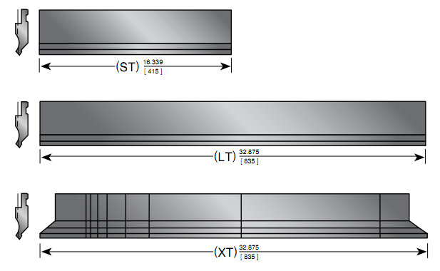
This is a fairly standard break down of sectionalized tooling: 100mm Left and Right Ear, 10mm, 15mm, 20mm, 40mm, 50mm, 200mm and 300mm. In addition most manufacturers offer a 415mm ‘Short’ Section and a 835mm ‘Long’ Section. By combining different sections a wide variety of possible lengths emerge.
