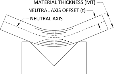
The K-Factor in sheet metal working is the ratio of the neutral axis to the material thickness. When metal is bent the top section is going to undergo compression and the bottom section will be stretched. The line where the transition from compression to stretching occurs is called the neutral axis. The location of the neutral axis varies and is based on the material’s physical properties and its thickness. The K-Factor is the ratio of the Neutral Axis’ Offset (t) and the Material Thickness (MT). Below the image shows how the top of the bend is compressed, and the bottom is stretched.

The K-Factor is used to calculate flat patterns because it is directly related to how much material is stretched during the bend. It’s used to determine Bend Allowances and Bend Deductions ahead of the first piece. Having an accurate idea of your K-Factor is key to designing good parts because it can anticipate Bend Deductions for a variety of angles without relying on a chart. Because of this it is often used by design software such as Solid Edge, Solid Works and Pro-Engineer, though Pro-Engineer uses a variation called the Y-Factor.
If you have a Bend Allowance (BA) you can derive the K-Factor from it. This is useful if you are transitioning from hand layouts to an advanced design software. Subsequently you can use the K-Factor to extrapolate allowances for new angles and radii.
Calculating the K-Factor
Since the K-Factor is based on the property of the metal and its thickness there is no simple way to calculate it ahead of the first bend. Typically the K-Factor is going to be between 0 and .5. In order to find the K-Factor you will need to bend a sample piece and deduce the Bend Allowance. The Bend Allowance is then plugged into the above equation to find the K-Factor.
- Begin by preparing sample blanks which are of equal and known sizes. The blanks should be at least a foot long to ensure an even bend, and a few inches deep to make sure you can sit them against the back stops. For our example let’s take a piece that is 14 Gauge, .075”, 4” Wide and 12” Long. The length of the piece won’t be used in our calculations. Preparing at least 3 samples and taking the average measurements from each will help
- Set up your press brake with the desired tooling you’ll be using to fabricate this metal thickness and place a 90° bend in the center of the piece. For our example this means a bend at the 2” mark.
- Once you’ve bent your sample pieces carefully measure the flange lengths of each piece. Record each length and take the average of lengths. The length should be something over half the original length. For our example the average flange length is 2.073”
- Second measure the inside radius formed during the bending. A set of radius gauges will get you you fairly close to finding the correct measurement, however to get an exact measurement an optical comparator will give you the most accurate reading. For our example the inside radius is measured at .105”
- Now that you have your measurements, we’ll determine the Bend Allowance. To do this first determine your leg length by subtracting the material thickness and inside radius from the flange length. (Note this equation only works for 90° bends because the leg length is from the tangent point.) For our example the leg length will be 2.073 – .105 – .075 = 1.893.
- Subtract twice the leg length from the initial length to determine the Bend Allowance. 4 – 1.893 * 2 = .214.
- Plug the Bend Allowance (BA), the Bend Angle (B<), Inside Radius (IR) and Material Thickness (MT) into the below equation to determine the K-Factor (K). For our example it comes to
K-Factor Chart
A K-Factor will typically range between 0 and .5 for standard materials and thicknesses though smaller and larger K-Factors are possible. To help you begin I’ve included a K-Factor Chart below which contains common K-Factor starting points, good for general fabrication, for steel, aluminum and stainless steel.
Radius Soft / Aluminum Medium / Steel Hard / Stainless Steel
Air Bending
0 - Mt. .33 .38 .40
Mt. - 3*Mt. .40 .43 .45
3*Mt. - >3*Mt. .50 .50 .50
Bottom Bending
0 - Mt. .42 .44 .46
Mt. - 3*Mt. .46 .47 .48
3*Mt. - >3*Mt. .50 .50 .50
Coining
0 - Mt. .38 .41 .44
Mt. - 3*Mt. .44 .46 .47
3*Mt. - >3*Mt. .50 .50 .50
The K-Factor of a 180° Bend (Hem)
The K-Factor for a 180° bend is going to be meaningless because it’s tied to the Outside Setback which approaches infinity as the bend approaches 180°. Because of this K-Factors are not used to calculate allowances over 174°. Instead a hem allowance of 43% of the material thickness is used. See our post on Sheet Metal Hems for more information.