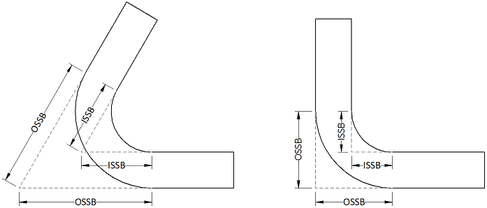
Understanding the Outside Setback of the workpiece is an important part of designing sheet metal parts. The Outside Setback is the distance from the apex of the outside mold lines to the tangent point of the outside radius. When the sheet metal is bent the inside radius pulls the edge of the material away from the apex of the bend. Because this is a geometrical function it does not change with a metal’s K-Factor the way Bend Allowance and Bend Deduction do. The Outside Setback is closely related to, but should not be confused with, the Inside Setback. The below image shows the difference between the Outside Setback (OSSB) and the Inside Setback (ISSB). As you can see these values are heavily dependent on the Bend Angle.

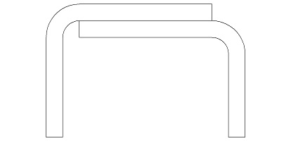
The Outside Setback is only considered in angles up to about 170 ° because as the angle approaches a 180 ° bend the values of the Outside Setback and Inside Setback approach infinity. This will throw off any Bend Allowance or Bend Deduction formulas you are trying to use to calculate your flat pattern. Because of this there are different considerations given to hem allowances. We have an entire post relating to hems if you are interested in their design and uses. Below you can see how these values become very large compared to the part itself as the bend approaches a flat. Below is shown at 170 °, the largest practical value for the Outside and Inside Setbacks.

Outside Setback Calculator
Below is our simple Outside Setback Calculator, it works by inputing the Material Thickness, Bend Angle and Inside Radius. It simply processes these variables through the equations we will discuss below. Note that the Bend Angle is the complimentary angle, not the included angle.
[swfobj src=”http://sheetmetal.me/wp-content/uploads/2011/04/Outside-Setback-Calculator.swf” width=”395″ height=”160″ align=”center” allowfullscreen=”false”]
Outside Setback Formula
The Outside Setback Formula takes into account only the geometries of bending rather than the physical properties of the metal. You will need to know your Material Thickness (MT), the Bend Angle (B<) and the Inside Radius (IR). The Material Thickness will be measured in decimal form, not by the gauge number. For more information on gauges and their decimal equivalents and tolerances view our Gauge Chart page. The Bend Angle will be something that you determine based on what the complimentary angle of your part is going to be. It is important to convert from the included angle to the complimentary angle before performing any calculations. The Inside Radius will be the finished radius of the included angle. For information on how the Inside Radius is determined see our post on the Air Bend Force Chart.
The Formula itself is rather simple:
Designing With The Outside Setback
As you can see below ignoring the Outside Setback when designing two mating flanges you will end up with interferences or poorly finished edges. On the left is the assumed design ignoring the outside and Inside Setbacks. If these values are ignored in the design you will have design issues. On the left you can see the interference left from ignoring the Inside Setback, on the right you can see an unfavorable overhang due to ignoring the Outside Setback.

When the Inside and Outside Setbacks are properly accounted for the finished design is superior in both fit and finish. The lack of interference means that the parts will fit together in a predictable fashion. The lack of an overhang means a smoother edge which is safer to handle and will look more professional.
