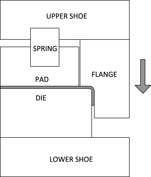
Wiping die bending, also known as edge bending, is performed by holding the sheet between a pad and die then sliding the wiping flange across the face pushing and bending the sheet metal which protrudes from the pad and die. The flange is driven by an upper shoe and the die is supported by a lower shoe. A spring between the pad and upper shoe grabs the metal before the flange hits it and holds the workpiece down during the bending process. If the flange has a feature associated with it, other than just a straight bend then a stronger spring will help prevent the metal from being pulled from the area between the die and pad. This will lead to less deformation when the piece comes out of the stamp. In our example below we are only showing a single section of a feature but in reality there can be flanges formed on any and all sides of the piece at the same time. This can lead to significant productivity gains. The Bend Angle is controlled by the stroke of the wiping punch. It’s necessary that the punch has the proper offset for the thickness of the material to prevent shearing. This method does not allow for over bending past 90 ° because of the tooling geometry. This also makes it difficult to work with harder materials which have a high Spring Back.

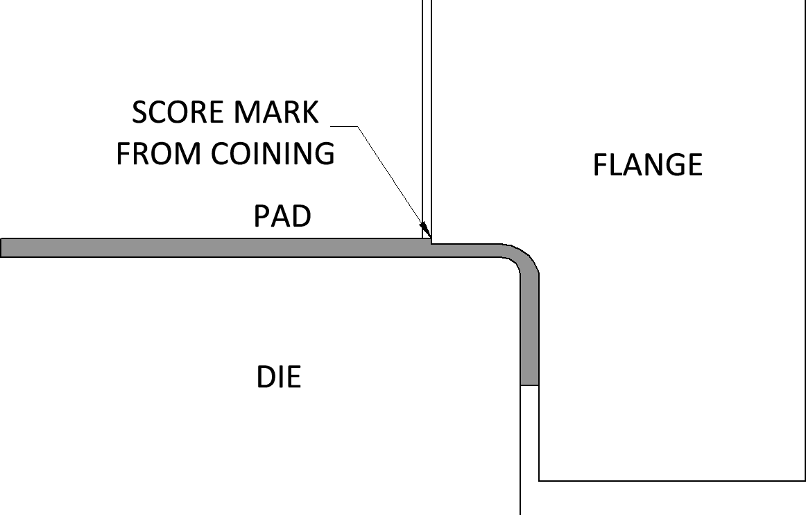
The main advantages to wipe bending are repeatability and that it requires less skill to perform the bend. Most dies will have locating features such as pins so the worker simply loads the flat piece into the press, aligning the necessary pins, then clears away from the press and engages the punch. The main disadvantage is that Spring Back compensation is rather limited. In an attempt to control the Spring Back the top of the bend is often coined by adding a return flange to the forming punch and putting the tooling under such pressure that it begins to flow. While this method does improve Spring Back it also can weaken the metal around the bend and leave a score mark at the edge of the return flange.

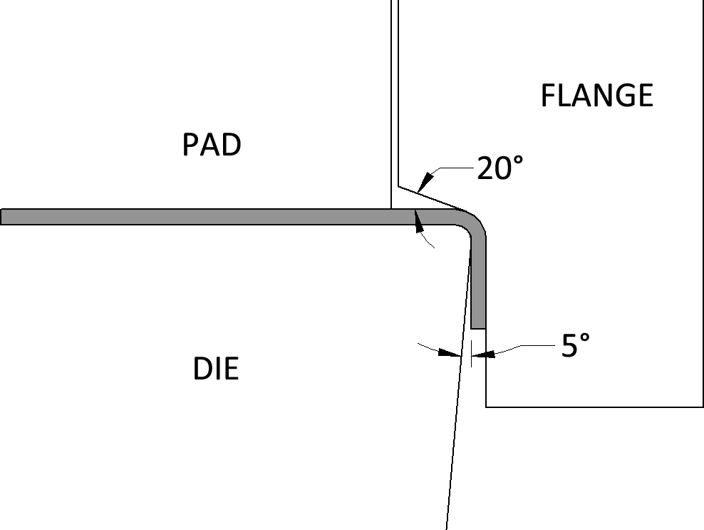
A better way to coin the radius is to modify both flange and the die. By adding an angle, 20 ° tangent from the radius, to the return flange it prevents the score mark and concentrates the pressure on the radius of the work piece. Additionally adding a 5 ° return to the die’s front face will allow for the Coining to take place more evenly.

Different Forms Of Wiping Dies
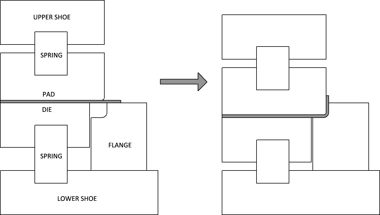
Wipe dies are not limited to down bends, by adapting the geometry of the Die, Pad and Flange you can achieve up and down bends, and even incorporate return flanges. Often times the benefit of wipe dies is that they do not require the work piece to be whipped up with the press brake. This usually means the piece is too large to easily handle, so when a design calls for an upward flange it is sometimes more practical to have a wipe die which can produce an upward flange, rather than having to flip the work piece. To achieve an up bend with a wipe die the flange is moved under the die and the die is spring loaded. When the force from the Upper Shoe is transfered to the work piece the die moves below the flange and creates an upward bend in the sheet metal. The same principles of over bending and edge Coining apply.

By modifying the bottom die to include a return relief, wiping dies can be made to easily and repeatedly form channel edges, presuming the size of the channel’s width and depth are equal.
As we’ve discussed wipe bending is not limited to just performing a down bend, specialized dies can be used to form bends on 2,3 or 4 sides of a piece. By sectionalized a center piece this operation can be made adjustable. While this is an expensive form of tooling under the right circumstances the productivity gains out weigh the initial cost.
Calculating Tonnage For Wiping Die
The tonnage required for a wiping die can be estimated with some degree of accuracy based on a rather simple formula which incorporates the Metal Thickness (MT), the Inside Radius of the Flange (RF), the Outside Radius of the Die (RD), the Tensile Strength of the Material (TS), the Length of the Bend (L). The metal thickness should be in decimal form, see our Gauge Chart for Gauge to mm and Gauge to inch conversion. The Flange Radius and Die Radius should be determined by your die design, take into consideration your desired corners, the material thickness (RF should be at least RD+MT) and the material itself. Too sharp of a radius and you could end up shearing the part. I would base your target off of an acceptable bend radius from the Air Bend Force Chart. The Tensile Strength is a well documented property of most shop metals and should be entered into this formula in the form of PSI. The output of the formula will be in Tonnage Required To Bend (T).
As with almost all fabrication formulas I’d recommend using this as a guide for tool selection and machine sizing preparation. Production should almost always be proceeded by a test piece.