Step Bending, or Bump Bending is a method for forming a Large Bend Radius in a sheet metal part, without the need for special tooling, by creating a series of highly open bends in close proximity. This method will have advantages over using a roller because the length of the rolled section can be controlled more precisely with high repeatability. The draw backs are that it takes some time to properly execute and is technically difficult. Each bend must be set up perfectly to prevent a misalignment from propagating through the part. because of these reasons hard tooling is preferable for non automated production. For automated production this method gives designers a significant level of freedom when designing parts. Before we get into calculations and tool selection we’ll need to define a few terms related to step bending.
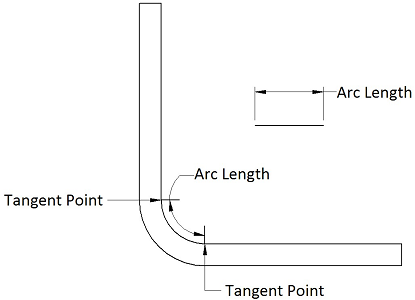
Arc Length
The Arc Length (AL) of a bend is the actual length of the inside radius measured from one tangent point to the next. It may help to think of ‘flattening’ out the inside radius. The arc length can be calculated using the Bend Angle (BA) and the Inside Radius (IR) using the following formula:

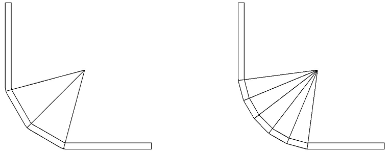
Bend Step
The bend step is the number of bends which will be used to form the radius. The more bends the smoother the roll. As you can see below the difference between 3 and 6 bends is rather significant. It should be noted that the Bend Angle is also halved from 30° to 15°. Choosing the right bend step is important because while more bends means a smoother radius it also means a more time consuming and technically difficult procedure. It should also be noted that the score marks from the bends will be more apparent on the inside of the bend compared to the outside.

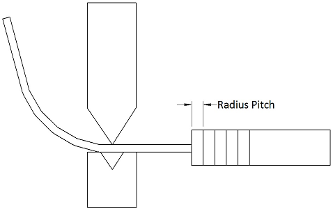
Radius Pitch
The Radius Pitch (RP) is the distance between each bend. In terms of programming your press brake it is the distance forward the back gauge will move between each bend. The radius pitch is easily derived from the dividing the Arc Length (AL) of the desired radius by the Bend Step (BS).

Die Selection
Selecting your tooling for a step bend follows a different process than that of regular bends. In step bending you will not penetrate very far into the die and you will want to make consecutive bends at close intervals so a smaller v opening is desirable for the die. Because we always want the work piece to sit flat on top of the die the optimal V Opening (V) is going to be twice the Radius Pitch (RP).
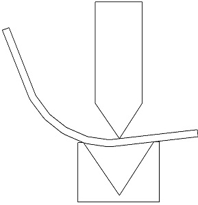
This formula should be seen basically as a maximum v opening because larger v opening will result in the work piece not properly contacting the die as shown below. This will also cause problems in contacting the back gauge, resulting in an inconsistent bend. However a smaller v opening will require more tonnage and form a smaller step bend radius. The smaller the radius is the more noticeable it will be on the final part. So the basic rule for selecting your v die is to find the first opening size below the optimal opening.

Punch Selection
Choosing the punch for step bending is a bit easier, because every bend is going to be an air bend the inside radius will be determined by the v opening rather than the punch tip radius. However it does make sense to choose a punch with a radius on the tip to minimize the score mark on the inside of the bend. Don’t overcompensate by choosing a large radius tooling though, the small v opening tooling will be damaged if you use a large radius tool.