Offset tooling allows two v bends to be formed closer together than regular Press Brake Dies would allow. This creates a z shaped profile in the sheet metal. This type of bend is also commonly referred to as a jog. The two basic forms of offset tooling are ‘Spring Up’ and ‘Horizontal’. Beyond these two forms there are three types of tooling, balanced, unbalanced and versatile types. The spring up type causes the material to move from a horizontal plane up to the Bend Angle, similar to a regular V bend operation except the rear of the work piece will move down instead of up. The horizontal type allows the work piece to stay level while the offset is formed. Spring up offset tooling is the more common version because it’s reduced thrust forces.
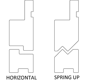
Spring Up Tooling
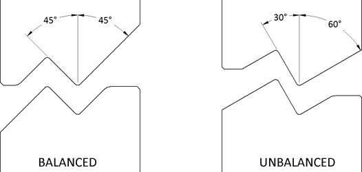
On balanced tooling there is no thrust force formed when forming the offset. A thrust force is when the punch or die experiences horizontal forces when forming the part. See the section below on horizontal thrust forces for a better illustration of this. On CNC controlled press brakes spring up tooling also allows bends other than 90° to be formed in the metal by controlling the depth the punch. Spring up tooling is limited to the depth of the offset that it can form. To avoid shearing or over stretching the depth of the offset should always be between 3 and 10 times the material thickness.
Spring up tooling does cause the work piece to finish at an angle to the press brake. This means for large work pieces if can be difficult to move the part down with the bending process. It also means that flanges with return bends on them can interfere with the brake. Unbalanced tooling addresses this in some fashion by splitting the 90° bend into 30° and 60° rather than 45° and 45°. While unbalanced tooling helps to reduce spring up it does cause some thrust, typically not enough to require a thrust plate, but it should be taken into consideration.
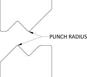
Creating an offset is intended to be a Coining operation and while the tonnage required to coin two bends in the sheet metal is often outside the limits of the tooling the higher the tonnage, the better the results. I would never recommend using over 80% of the tool’s maximum tons/foot. The punch radius on spring up tooling is measured at the ‘tip’ on the punch and die and should be determined in the same manner as when Air Bending. So use the Air Bend Force Chart to select an inside radius near the ideal tonnage area.
Horizontal Tooling
Horizontal Tooling is beneficial when creating offsets in large parts because it allows the material to stay level during the forming process. The profiles of the punch and die are relatively simple to manufacture when compared to spring up tooling, often making it a cheaper alternative. Horizontal tooling should only be used for offsets less than 3 times the material thickness. The punch tip is almost always sharp, unlike the radii on the spring up type. Horizontal tooling will never form a 90° offset, to try and tool this scenario would result in the shearing of the sheet metal. 70° should be taken as the maximum offset angle though even this is sometimes damaging to the work piece.
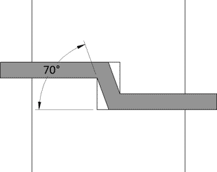
As horizontal tooling closes down on the sheet it causes the sheet to angle slightly, this creates a slide for the punch to move down which translates to a thrust force on the punch. This force is stronger for thicker metals and larger offsets and should be considered when selecting tooling. Installing a thrust plate on the bottom die can negate this effect, however it limits the length of your offset flange.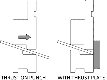
Now that you are familiar with the basic types of offset tooling let’s examine the process of proper tool selection. Often times engineering drawings, or design requirements will call for an offset other than 90°, selecting and designing this type of tooling is done with the help of some simple trigonometry.
Tool Selection
First we’ll define a key dimensions for designing offsets. The Part Offset (PO) is the dimension measured from the inside of the offset to the bottom of the workpiece. Then Angle (A) of the offset. The Tool Offset (TO) is the designed offset of the tool, this is how almost all tooling is categorized. The Penetration (P) of the tool is the depth past the surface of the workpiece the punch tip passes.
To find the Optimum Die Width for achieving the desired Angle (A) simply take the angle and divide it by .7071.
To determine the Penetration (P) you can use the below formula:
With these formulas you can create a variety of offsets with the same set of tooling.