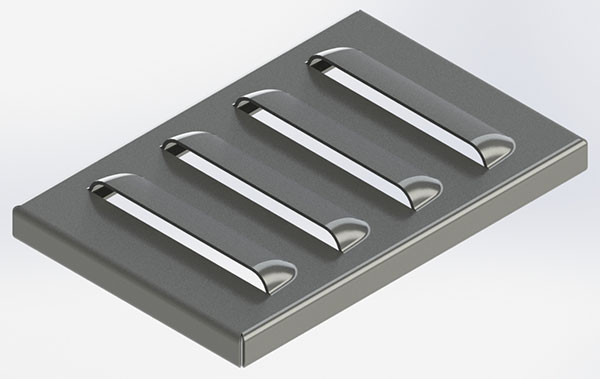
A louver in sheet metal design is typically a formed feature made with a punch press incorporating a top and bottom die. When formed the metal is slit across the length of the louver and forced up into the die. The sides of the feature will not be slit. This forms a raised window in the part which is protected on three sides and open on the fourth. This is the most common form of louver and is known as a closed end straight back louver.
Forming of Louvers
Punch Press
Forming a louver on a punch pres is by far the easiest method, though it requires large and expensive tooling. If you are designing a piece which uses many louvers, it is certainly desirable to have it manufactured on a punch press over a press brake.
Press Brake
There are two ways to form a louver on a press brake. The first is a simple adaptation of the punch press tool and die, where the tooling is flipped, die on bottom and punch on top, and moved to a press brake. The tooling is flipped because the flat top of the die makes it easier to hold and position the work piece while the punch comes down. The major difference between forming a louver on a press brake as compared to a punch press is the speed at which the tools make contact and form the work piece. In a punch press the action is quick, taking a fraction of a second, and at this speed the straight exposed edge of the louver is cut cleanly. The action of a press brake is much slower, taking a second or two to form the feature, because of this a slit where the window is formed is needed. Without this slit the forming process would rip and pull the work piece away, leaving a less than desirable finished product.
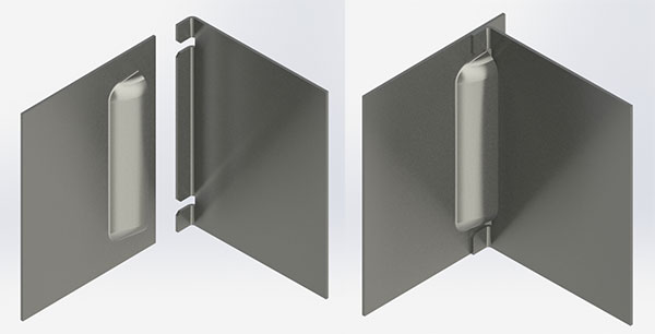
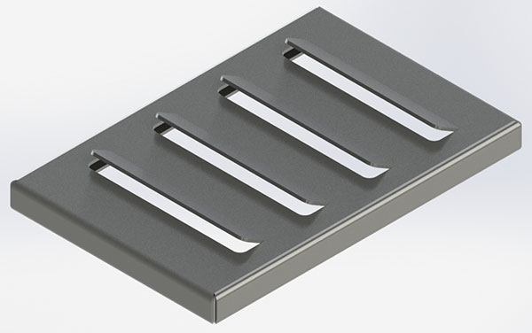
There is a second method of creating louvers which does not require special tooling, and may be ideal for low quantity production or prototype runs where specialized tooling is not available. With this method the work piece is cut away on three of the four sides of the louver and standard tooling is used to create a bend in the part. This method does not have the advantage of closed sides, but it does offer a quick and easy alternative.
Design of Louvers
Size
The first thing to consider in your design is the availability of tooling. A louver is a formed feature and therefore requires custom tooling to fabricate. If it is on a punch press you will be limited by the size of tool allowed on the press, minus and necessary clearances or tool holding. If you are manufacturing in house now what size louvers your company has. If you are sending your parts out for fabrication elsewhere know what the standard sizes are for the industry. Model your louvers around these designs as the louver is not a feature which can be worked through, it is a one shot deal.
Spacing and Clearance
The most common mistake made by designers is to not consider the spacing between louvers. The punch and die will need some degree of clearance around the feature in order to old down the work piece while the louver is formed. if another louver is placed inside this working envelope it will be crushed by the punch and die, ruining the work piece and potentially damaging the tooling. Before designing a piece with a louver understand the working envelope and space your louvers with a reasonable degree of safety. With this said modern tool makers are aware of this restraint and have achieved some impressively small working envelopes for louver tooling.
Be careful to locate the louvers far enough from the edge of the work piece to allow for the punch and die to fully engage the sheet metal before forming. Additionally you should ensure that the louver is clear of flanges as it can interfere with the tooling required to form the flange.
Design Advantages
The first and most obvious advantage of a louver is that it allows venting of air through the work piece while offering some protection from the elements. The feature is usually smooth, and acceptable for the outside of machinery as it won’t catch on something brushing against it.
A second application of louvers is to use them as assembly guides. A well designed louver and mating flange can be used locate parts in an assembly before fastening or welding the parts together. This application may require some trial and error before achieving design geometry which fits together as desired.