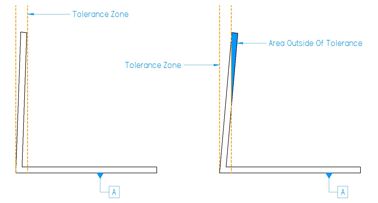
The tolerance specified by the engineer or designer tell the brake operator how much variation in the particular bend is allowable. Typically this information is located in the title block of a drawing. Angle tolerances are typically denoted by ±x.xx °. The ± symbol means ‘plus or minus’ meaning the angle can be bent both over or under the desired angle and still be functional. Generally ±1.0 ° is typical and most manufacturers will be able to hold this. When it comes to angles there are three recognized values for measuring tolerances beyond the actual angle, they are: angularity, perpendicularity and parallelism. These tolerances are usually denoted outside of the title block in what is called a feature frame. Here we will take a quick look at a basic feature control frame and its elements. The feature control frame is made up of 3 sections, a symbol denoting the type of control, the actual tolerance and modifier and the reference datum plane. Modifiers

Angularity measures whether or not the entire face, axis or plane of the feature falls within a certain offset from the intended angle referenced from another plane. Perpendicularity is angularity as it pertains to a 0 °, 90 °, 180 ° and 270 ° angles. The angularity and perpendicularly is important when fitting pieces together. Parallelism ensures that a plane stays within two parallel planes set apart an equal amount from the reference geometry. For more information on GD&T terminology, symbols and modifiers click here.
Angularity / Perpendicularity

Parallelism
