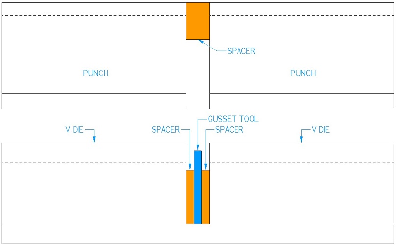
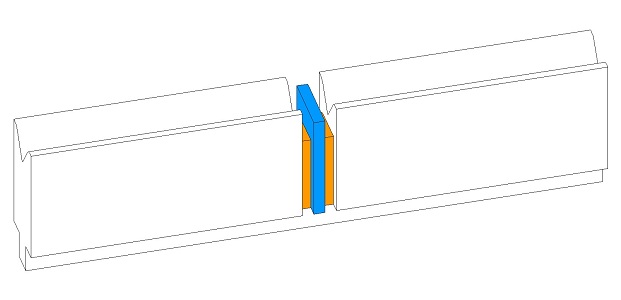
Sheet metal gussets are formed with special tooling which has a ridge going across the v opening. The punch is split to the left and right of the ridge as to not be damaged while forming. The sheet metal is bent normally across the v opening except in the area where the ridge is. Typically a spacer separates the ridged section from the rest of the v die, this provides a consistent relief for the sheet metal being bent. It is important to note that the punch needs to also be spaced apart in the same fashion as the die, this will prevent very serious damage. Where the tooling is split the ridge forces the metal into the bend forming a triangular section. This triangular section is known as a gusset and can be used to stiffen or strengthen a bend.

By changing the shape of the forming tool, shown in blue, you can control the finished shape of the gusset. For example a straight tool like the one shown will give you a triangular gusset. A ‘V’ shaped forming tool would give you a square shaped gusset, and so on. Because you are deforming the metal significantly it is not uncommon to see rounded tips on the forming tool, to allow the metal some relief from the process.

The spacers used will typically be rather thin, approximately .025” thick on each side of the gusset. Too thin of a spacer and the gusset tooling will tear through the workpiece and weaken the part. Too much of a spacer and the gusset won’t do much in the way of strengthening the work piece. Typically the gusset material can be stainless steel and should be slightly lower than the top of the die, this will allow you to set your workpiece on top of the die and align it with the back stop before bending.
Forming A Gusset In Solid Edge / Solid Works
Below I’ve included some links as to how to properly design gussets in common design softwares:
Solid Works
Scroll down for video on forming gussets.
Solid Edge
Has a lot of information on sheet metal design in Solid Edge, including gusset forming.