Angles, and the math and terminology associated with them, are an everyday part of being a sheet metal engineer and Brake Press operator. While it’s not necessarily required that you understand all of the geometry and trigonometry associated with triangles it will benefit you to know the basics. The first set of terminology relates to the general shape of the finished Bend Angle.

Acute Angle: A bend which is less than 90 °.
Typical Acute Angle Tooling profiles are 30 °, 45 °, and 60 °, though there is custom tooling, and Air Bending allows for the forming of any angle larger than the angle of the punch tip.
Right Angle: A bend equal to 90 °.
Right angles are the most common feature found in most sheet metal fabrication. Tonnage charts, Bend Deduction, Bend Allowance and other forming calculations and charts often refer to a 90° bend. This type of angle can also be referred to as a square bend.
Obtuse Angle: A bend greater than 90 ° but less than 180 °.
Obtuse angles are almost always formed by Air Bending because tooling is rarely customized to meet the requirements for Coining or Bottom Bending angles larger than 90°. This is because this kind of tooling would only be good for the obtuse angle, compared to 90° tooling which is good for forming the obtuse angle as well as tighter bends.
Reflex Angle: A bend greater than 180 °.
A reflex angle is typically only referenced in design because they are almost always fabricated as an obtuse bend. This is done by draftsmen and engineers to provide clarity on prints. It is sometimes not practical to show the internal angle of a part clearly on a print. Using the reflex angle allows them to move the leaders to better positions. Pay attention when programming the press brake; know which angle you are reading.

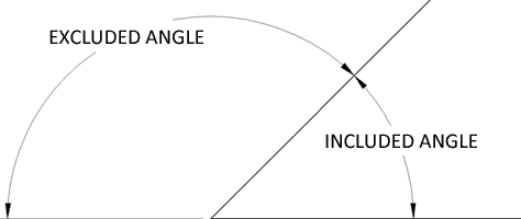
Included Angle
The included angle is the most intuitive for press brake operators to understand. This is the measurement between the inside mold lines of the work piece. Tooling is referred to by the minimum included angle it can form through Bottom Bending or Coining.
Excluded Angle
The excluded angle is the measurement between the outside mold lines and is often realized as the counterpart to the included angle. Most calculations such as Bend Deduction and Bend Allowance are done using the excluded angle, so it is important to know which you’re dealing with.