Acute angle tooling generally refers to any tooling which is intended to reach a bend greater than 90°. While custom sizes are always available this tooling is typically stocked at 30°, 45° and 60°. Typically acute tooling is used for Air Bending parts. This is because the tonnage required to coin a work piece will typically exceed the tool’s tonnage limits. Acute angle tooling typically has lower tonnage limits compared to standard tooling because he longer flanges required to form an acute die means a thinner base, and higher leverages against it. Bottom bending is also uncommon in acute angle bending for both tonnage and tooling reasons. Standard acute angle tooling does not have the built in tooling clearance required to bottom bend, so custom tooling would be necessary.
Forming
While acute angle tooling’s primary use is for creating bends over 90°, there is nothing wrong with using it to air bend any angles in between. Reliefs in acute tooling are often minimal, because the tooling is already naturally thin, but even a slight relief can open the door to a number of new bend geometries. Acute angle tooling can also be an alternative to a straight punch for closing a profile. And finally acute angle tooling is almost always used at the start of a hemming operation.
Punch Selection
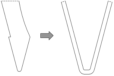
When an acute bend is formed a small flat section under the punch tip is created in place of a true radius. This flat section becomes more pronounced the sharper the bend. This effect is different than that of the multi-breakage phenomenon found on Large Radius Bending. The size of the flat section is directly related to the size of the punch tip. The flat section will typically be twice the radius of the punch.

Above you can see how an acute bend is actually formed with a standard 30° punch and die. Again the flat section on the inside of the bend is going to finish twice the radius of the punch tip. While this generally does not affect the bending process in most metals it can have a significant impact when bending aluminum or similar metals. Aluminum has the tendency to crack around the outside surface due to circumferential strains. This cracking is not only unappealing, but can weaken your part. In order to minimize this cracking, the flat section of the acute bend should be at least twice the material thickness. So when dealing with aluminum you will want to choose a punch tip radius of at least 4 times the material thickness.
Die Selection
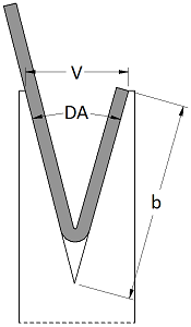
You will select your die width with the same principles as a regular Air Bending operation with the one major exception of minimum flange lengths. Use an Air Bend Force Chart to select the appropriate die width for your desired finished radius. Because most force charts are set up for bending 90° bends in order to find the minimum flange length you will have to employ a bit of trigonometry. We are basically looking for the shortest flange will still be supported at the bottom of a bend. This formula uses the V Opening (V) and the Die Angle (DA) as well as the trigonometric functions, tan and sin to find the Minimum Flange (b). Also note that we are measuring to the apex of the bend.
